

2021 PV Module Reliability Scorecard
Mechanical Stress Sequence (MSS)
Key Takeaways
- Module susceptibility to cell cracking depends on many factors and results are nuanced. In general, PVEL has found that:
- half-cut cells perform better than full cells.
- 120-cell designs perform better than 144-cell designs.
- monocrystalline cells perform better than multicrystalline cells.
- multi-busbar cells perform better than 3BB, 4BB or 5BB cells;
- interdigitated back contact (IBC), cadmium telluride (CdTe) thin film, and glass//glass module technologies have also shown minimal degradation.
- Modules can experience significant cell cracking during MSS testing using the ideal mounting: rails running the width of the module in one-quarter segments on either end. For these modules alternative configurations used in trackers and roof mounts are very likely to exhibit a greater degree of cell cracking.
- The installation manuals for select modules do not include PVEL’s standard MSS mounting configuration. These modules achieved Top Performer results when tested according to the manufacturer’s manual. PVEL encourages review of PQP test reports and installation manuals for mounting guidance.
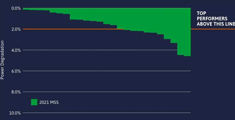
- Compared to PVEL’s historical database of DML+TC50+HF10 results, the results of median power loss from MSS, which adds SML to the start of the sequence, increased by almost 50%.
2021 Top Performers
Manufacturer
Model Types
Boviet
BVM6612M-xxxL-H-BF (BVM6610M-xxxL-H-BF) ;
BVM6612M-xxxL-H-BF-DG (BVM6610M-xxxL-H-BF-DG) ;
BVM6612M-xxxL-H-HC-BF-DG (BVM6610M-xxxL-H-HC-BF-DG)
BVM6612M-xxxL-H-BF-DG (BVM6610M-xxxL-H-BF-DG) ;
BVM6612M-xxxL-H-HC-BF-DG (BVM6610M-xxxL-H-HC-BF-DG)
ET Solar
ET-M672BHxxxTW (ET-M660BHxxxTW)
First Solar
FS-6xxxA
Jinko
JKMxxxM-7RL3-V
LG Electronics
LGxxxN1C-N5 (LGxxxN1C-V5)
LONGi
LR4-60HPB-xxxM ;
LR4-72HBD-xxxM (LR4-60HBD-xxxM) ;
LR4-72HPH-xxxM (LR4-60HPH-xxxM)
LR4-72HBD-xxxM (LR4-60HBD-xxxM) ;
LR4-72HPH-xxxM (LR4-60HPH-xxxM)
Maxeon/SunPower
SPR-Axxx-G-AC (SPR-MAX5-xxx-E3-AC, SPR-Axxx, SPR-MAX5-xxx)
Phono Solar
PSxxxM4GFH-24/TH
Q CELLS
Q.PEAK DUO L‐G5.2 ;Q.PEAK DUO BLK ML-G9+
Seraphim
SRP-xxx-BMA-BG
Note: Manufacturers are listed in alphabetical order. The tested product is listed first. Variants for which the test results are representative are listed in parentheses. In some cases, test results were not available at the time of publication.
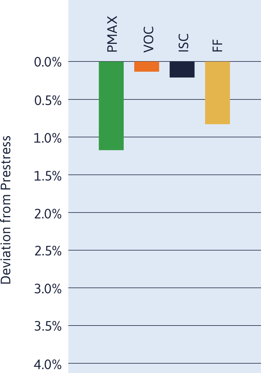
Power Degradation for Each Model Type
About the Test
Background of the Test
Excessive thermal and mechanical stress can cause microcracks to form in PV cells. Stress can occur during: cell soldering, lamination, and other module manufacturing processes; exposure to temperature fluctuations, wind, snow, hail, and other environmental conditions; and/or physical damage in transportation, installation, or maintenance. If cracks restrict the flow of current through the cell, modules can produce less energy. They can also form hotspots, introducing safety risks.
Test Procedure
MSS, added to PVEL’s PQP in 2019, combines tests for static mechanical load (SML), dynamic mechanical load (DML), thermal cycling, and humidity freeze to create, articulate and propagate cracks in susceptible modules as would occur in field conditions.
For SML, modules mounted on two rails and secured at typical ground-mount clamping locations undergo three rounds of one-hour downforce and one-hour upforce at 2,400 Pa. For DML, modules are subjected to 1,000 cycles of alternating positive and negative loading at 1,000 Pa. To simulate environmental stress, modules undergo 50 thermal cycles from +85°C to -40°C, then 10 cycles of humidity freeze, high heat and humidity followed by a rapid drop to freezing temperatures. MSS aligns with IEC TS 63209-1:2021 for extended reliability testing. See PVEL’s white paper, Cracking Down on PV Module Design: Results from Independent Testing, for more details.
Lessons Learned from Failure
The Problem
Consequences include less energy output if cracks restrict the flow of current, local hotspot formation leading to accelerated backsheet degradation and delamination, and increased risk of ground faults or arc faults.
Projects Facing the Greatest Risk
Regions prone to wildfires, hail, hurricanes, and tornadoes are exposed to heightened risk. Climate change and extreme weather events have made these risks a global phenomena.
How to Detect Failure
Cell cracks appear as dark, discolored, broken lines or areas in EL images.
An Example from the Field
System size: >10 MW
Type: Ground-mount
Location: Southern U.S.
Failure mode: Cell cracks
When a tornado struck a solar power plant in the southern U.S., PVEL conducted EL imaging in the field to assess the damage to the PV modules. Extensive cell cracking occurred throughout the site, which triggered a legal dispute.
Consulting PQP reports before procurement would have helped the buyers select PV modules that were more likely to withstand common weather events in this region.
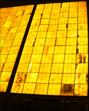
This EL image taken by PVEL in the field reveals cracks in the cells of a PV module.
An Example from the Lab
In the images displayed here, some inactive areas are immediately visible following the SML test sequence. Damage becomes more noticeable as the module proceeds through DML and TC50+HF10 testing.
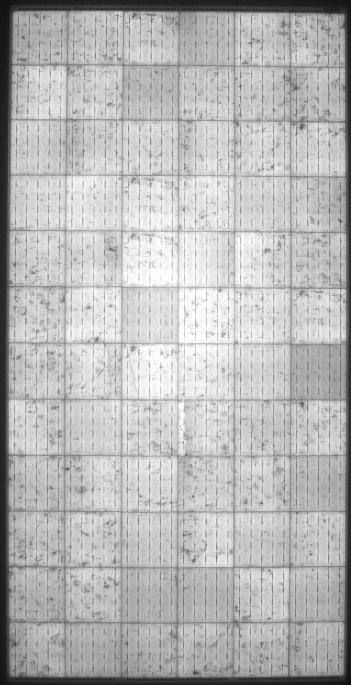
Prestress
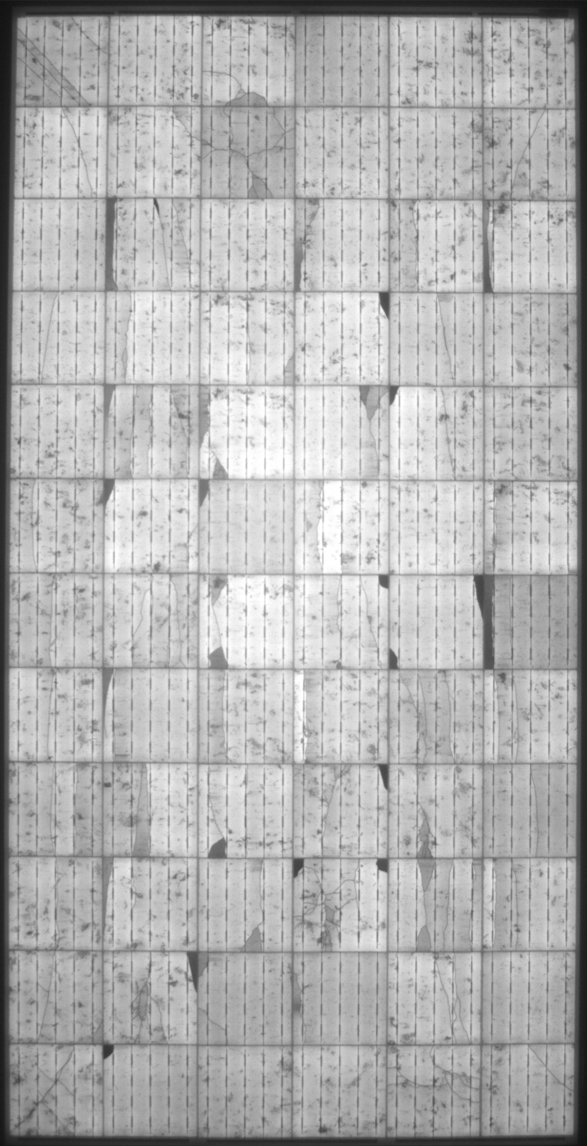
SML
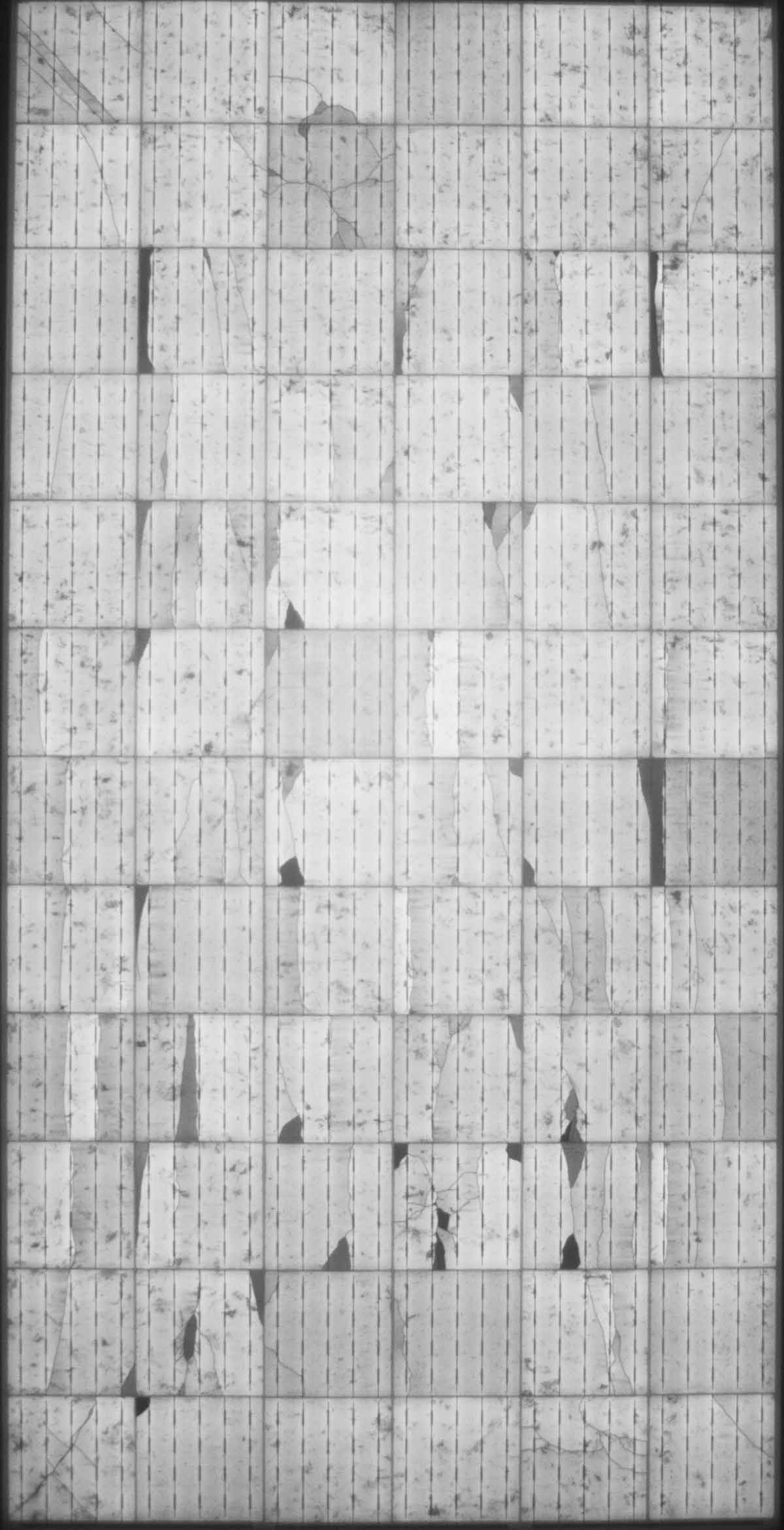
DML
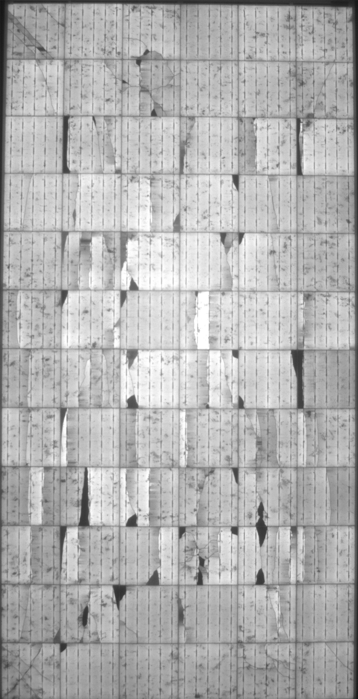
TC50+HF10
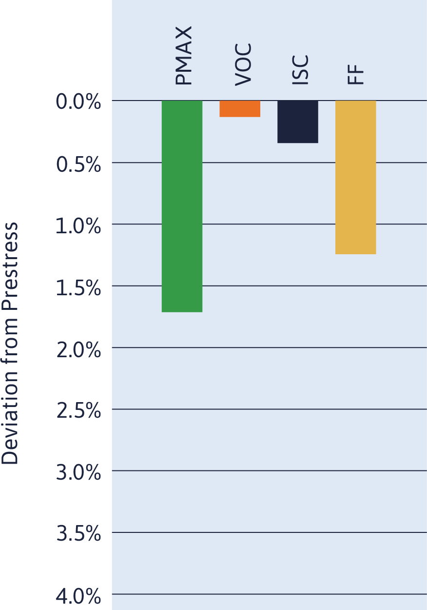
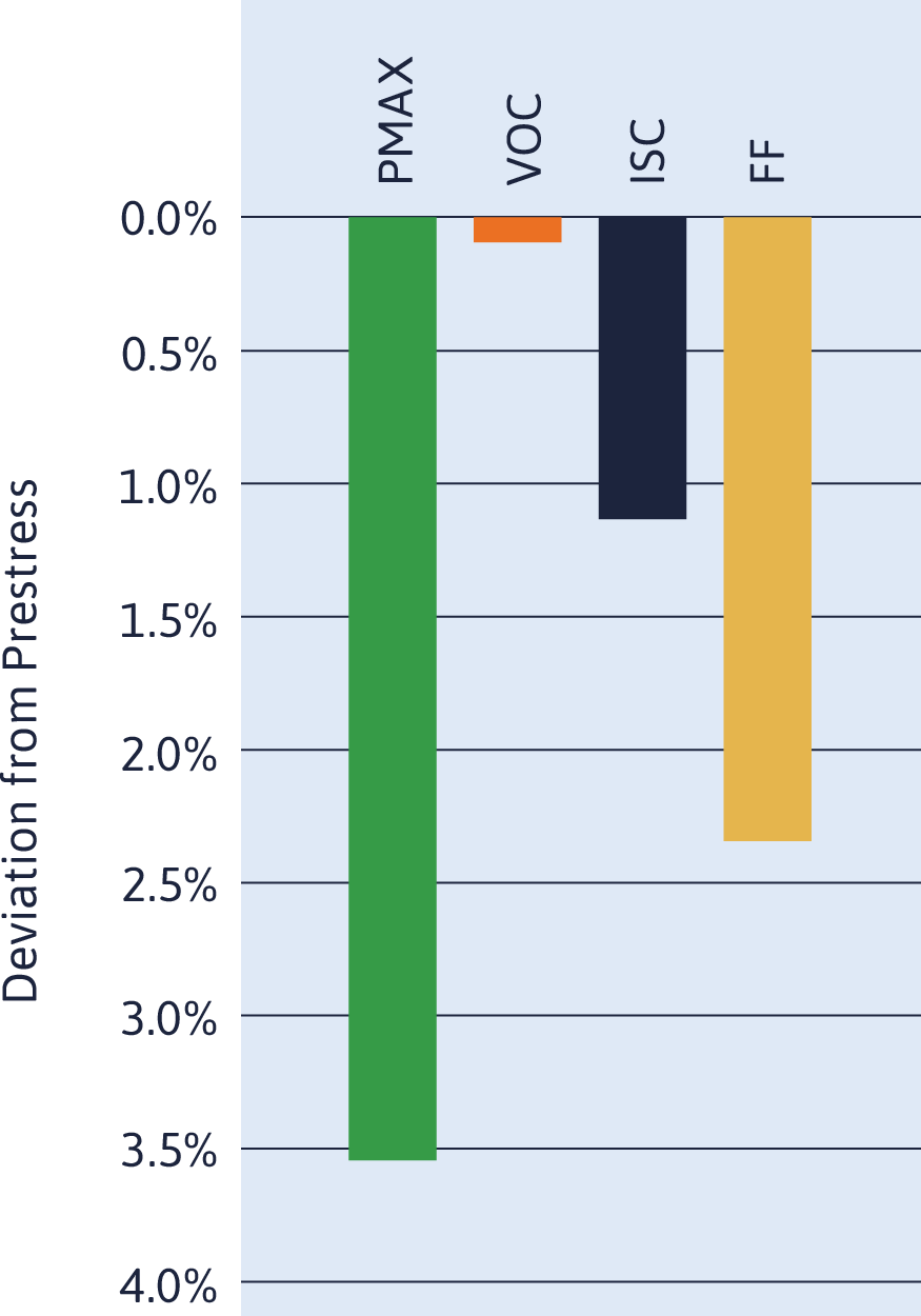
Power Degradation After:
SML: 1.2%
DML: 1.7%
TC50+HF10: 3.6%
Learn something new?
Share it with your network.